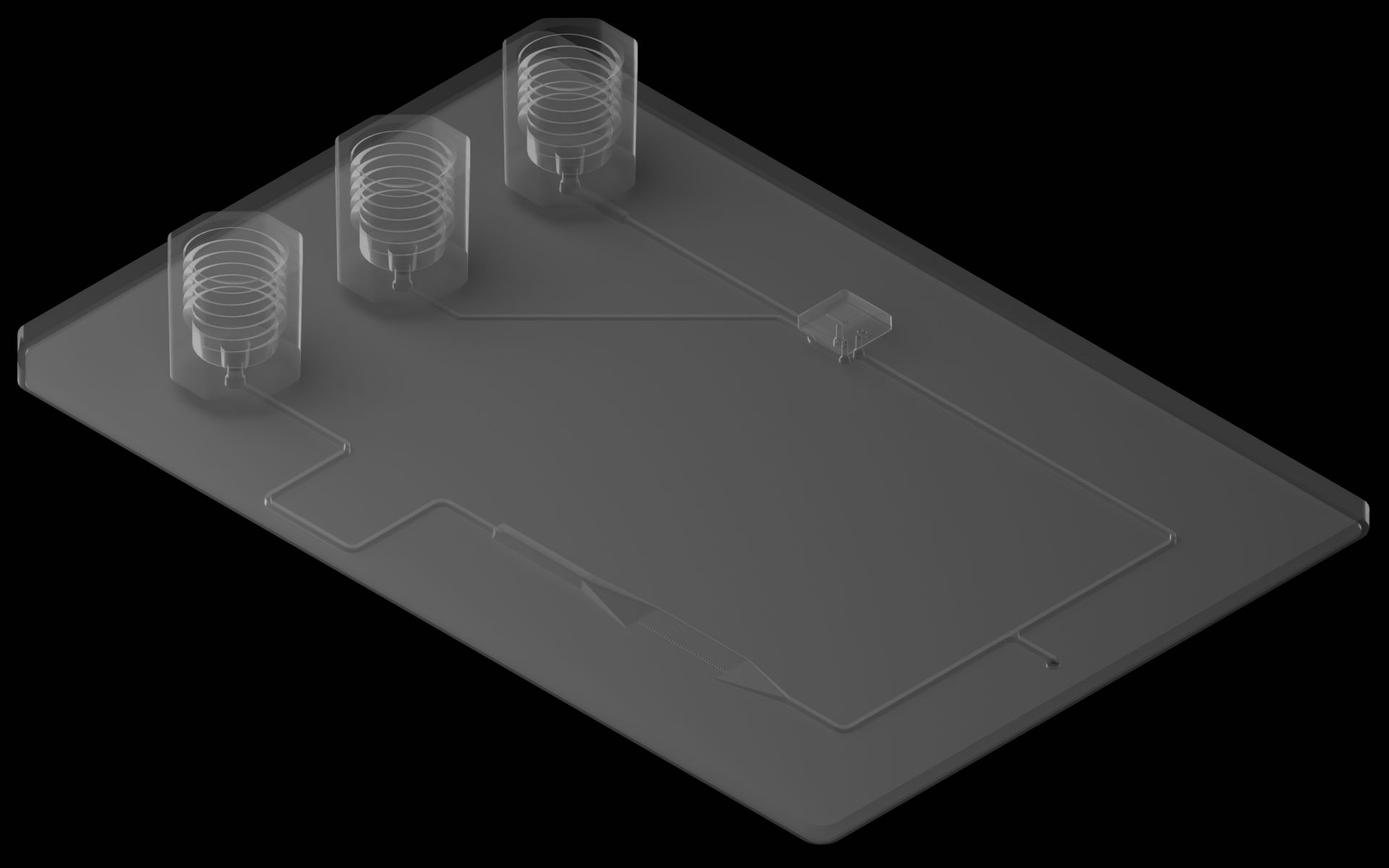
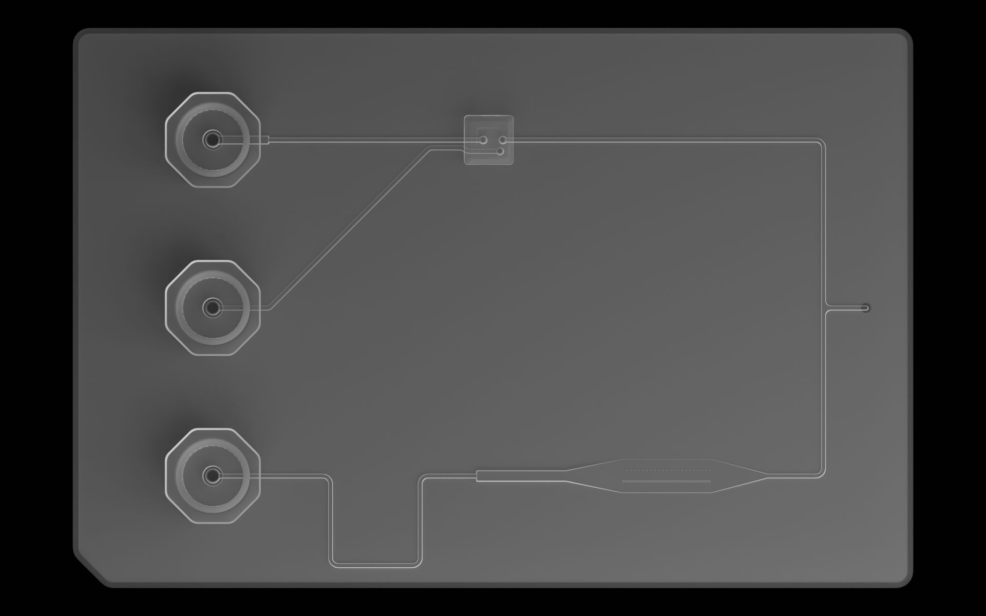
Our development platform is the best way to transform your microfluidic device concept into a reality. Reduce engineering effort and rapidly cycle through design iterations to arrive at a scalable product design faster than ever.
Production-quality prototypes in 3 days.
Ensure compatibility with existing lab standards and unlock zero-charge expedites.
Focus on your science instead of reinventing the wheel. Our components solve the most common challenges in microfluidic development.
Transition molding is our proprietary technology that allows us to prototype microfluidic devices in scalable materials from day one. We start by fabricating an aluminum tool with the inverse of your microfeature geometry in a fraction of the time of standard processes. Then we use our proprietary molding technique to replicate microfeatures from the tool into thermoplastic devices, ensuring your geometry is consistent, whether it’s the first part, or the 1000th. After molding, we can post-machine any additional features or thru-holes that can’t be fabricated during the molding process.
Our core formats are the best way to speed up the microfluidic prototyping process. They are each designed for maximum compatibility with our embeddable components, accessories, and standard lab equipment. Also, all devices that fit within our core format guidelines are automatically upgraded to a one week turnaround for no extra fee. The standard formats we currently offer are:
Our library embedded components will allow you to use pre-built solutions for many of the basic challenges in microfluidic design, like sample collection or interfacing to external equipment. The goal is to allow you to focus on the microfeature design inside your device, instead of worrying about challenges that have little to do with your core science. When you are ready to scale up, we can provide components in quantities of up to millions per year to ensure a smooth transition to high volume production.
Receive a quote with design-for-manufacturing feedback in 24 hours or less. Quantities, materials, and component choices can all be adjusted on-the-fly with our dynamic interface.
Parallel Fluidic produces ready to use microfluidic prototypes. In order to achieve our rapid turnaround times and ensure compatibility with Parallel components and accessories, we produce devices in the format described below. If you need something different, reach out! We may still be able to produce your device.
Components are discrete elements that can be emedded into a device to accomplish a specific microfluidic objective.
The fluidic layer is the main body of a device, and contains the custom microfeatures used to achieve a particular fluidic outcome.
A cap seals the fluidic layer to form continuous channels and features through which liquid can flow. The cap can be either a thermally bonded thermoplastic layer in the same material as the body, or an adhesive backed layer with specific properties.
Review our manufacturing guidelines to inform your design process before submitting a design. They will ensure your prototypes have the best chance of success and help to reduce cost in the manufacturing proces.
Devices can be delivered in your preferred setup:
A fully sealed device that is ready for flow.
A single fluidic layer containing microfeatures that are open on one side. Uncapped parts are great if you want to add reagents, modify surfaces, or cap the device with your own material.
Parts should be designed within the set of guidelines described below to best fit in the transition molding process. Most of these requirements are equivalent to those faced in high volume techniques like injection molding. This overlap helps to make sure that your prototypes are representative of devices that can be manufactured at full production quantities.
While designs that fit within the guidelines will lead to the best chance of success, we can often accomodate designs that requires tolerances or features outside of the standard workflow. Upload your design to the portal and we'll be in touch to discuss your requirements.
A device can have any footprint between 10 mm x 10mm and 127.76 mm x 85.48 mm, the standard size of a microplate as defined by the Society for Laboratory Automation and Screening (ANSI/SLAS 1-2004: Microplates — Footprint Dimensions).
The thickness (Z) of the fluidic layer can be anywhere between 1 mm and 3 mm. Our recommended thickness for maximum compatibility with components, capping, and high volume manufacturing processes is 1.5mm.
Custom device dimensions and shapes are possible, but we also offer a set of pre-defined device footprints, our Core Formats. These formats are sized to be compatible with existing lab infrastructure and also guarantee the option to use pre-built Components.
Microfeatures are the custom channels and geometry designed to maniuplate liquid inside of your device. The design requirements for these features are driven by the fabrication method used to create the master tool for your device and the transition molding technique used to create replicates.
Aspect ratio is the ratio of the height of your channel (H) to the width of your channel (W) when viewed in cross section. It is one of the most important parameters to keep in mind because its limits help to inform the rest of your design decisions.
Aspect ratio can have a major impact on the final dimensions of a capped channel. Generally, as the width of an unsupported capped area increases, the amount of cap deformation during the bonding process increases. If possible, keeping channel aspect ratios close to 1:1 will allow tighter tolerances and more consistent results.
Draft is the angle of taper that must be added to vertical walls and features. It is critical because when a plastic part is molded, it shrinks onto the mold as it cools. The shrinkage causes the plastic part to grip onto any proud features in the mold, and can prevent the part from releasing. By adding taper to vertical surfaces, the sticking effect is reduced and the part can be safely removed from the mold.
The most common draft angle we use at Parallel is 5 degrees. Keeping draft angles consistent can help to reduce the cost of a device iteration.
Features are the custom channels and geometry designed to maniuplate liquid inside of your device.
One of the advantages of our transition molding technology is that we can form channels with design freedom in three dimensions. Smooth tapering surfaces, varying heights, and domed features are all possible in our process.
Vias are the through holes that connect your microfeatures to the exterior of your device. In our process, vias are typically drilled during the post-machining process and have their own set of design constraints.
Posts are proud cylindrical microfeatures inside of your device.
Wells are receessed cylindrical microfeatures inside of your device.
The plastic device shrinks onto the mold during the cooling phase of the molding process. If a device contains a large number of wells, the shrink force rises dramatically, making it impossible to remove the device from the mold. We recommend adding 2 degrees of draft to each well when large arrays are required.
The tolerances for the transition molding process are divided into two categories. Microfeatures are the small fluidic features that will be molded inside of your device. Macrofeatures are larger dimensions such as outer device dimensions or via-to-via positions.
Cap edges should be offset from all edges of the fluidic layer (including through holes) by 500 µm to prevent alignment challenges and delamination risk.
Our standard materials are appropriate for different microfluidic applications. Review the downloadable datasheets to compare different optical, mechanical, and thermal properties.